How Faulted Circuit Indicators and Line Sensors Have Evolved Over 75 Years
What is a Faulted Circuit Indicator?
Faulted circuit indicators (FCIs), also known internationally as faulted passage indicators, are devices that have helped electric utility companies identify and locate faults on power grid systems since the mid-1940s.
How Faulted Circuit Indicators and Line Sensors Work
FCIs allow utility companies to more quickly repair issues related to faults and reduce electrical outage time.
- Faulted circuit indicators attach to a conductor, measure the magnetic field, and display an indication of a fault when measurements fall outside normal parameters.
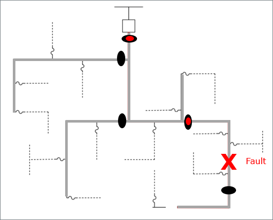
- When a fault occurs downstream of an FCI the current through the conductor increases and the FCI senses the increased magnetic field.
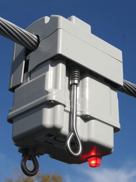
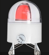
- If the increase in the magnetic field is high enough, the FCI displays a visible indication such as a bright red shape or a lit LED. However, if the fault happens upstream from the device, it doesn’t see the overcurrent and no visual indication appears.
- By looking at the different FCIs on a circuit, linemen can narrow down the fault location, reduce patrol time, and speed up restoration.

In the years since the first fault indicators were introduced, numerous technology enhancements have contributed to their evolution and spawned a new category of grid monitoring products – line sensors.
Wireless FCIs and today’s line sensors are significantly better products due to a series of five important enhancements made over decades.
Enhancement #1 – Automatic and Timed Reset FCI Functionality
The first FCIs had to be reset manually. When patrolling a distribution line, crews needed to reset each sensor that displayed a mechanical target for the fault.
Eventually, fault indicators were improved to include automatic or timed reset functionality.
- Automatic reset allows the FCI to reset its display when normal load current resumes on a conductor.
- Timed reset enables the user to select a time period, such as 4 or 8 hours, to reset the display, giving utilities more time to view indications of momentary faults.
Today’s FCIs have more intelligence and usually reset based on sensing that normal load current has resumed.
Enhancement #2 – Refined Fault Detection
Inrush current (the instantaneous surge of current when electrical equipment is turned on) from closing a breaker or recloser often caused early FCIs to incorrectly indicate a fault. Today’s FCIs use improved fault detection algorithms to distinguish inrush current from fault current and only trip the display for faults.
Higher levels of current on some feeders made it difficult to detect faults using a fixed fault threshold. In the late 1970s, some fault indicators started to use di/dt (current rate-of-change) as a fault detection method in conjunction with current thresholds to address this issue.
These fault detection improvements are used in FCIs today and algorithms continue to be fine-tuned by design engineers in order to decrease the frequency of incorrect fault indications.
Enhancement #3 – Greater Fault Display Visibility
Early FCIs used mechanical targets with red shapes for visible fault indications. Mechanical displays on fault indicators were not easy to see, especially in the dark, so FCI vendors worked to improve display visibility.


The advent of LED technologies in displays allowed fault indicators to be seen from much greater distances and in the dark and they could also flash different colors or patterns for permanent and momentary faults.
While visibility was greatly improved, the LED display increased power needs in the faulted circuit indicators. As a result, manufacturers integrated newer battery technology and line powering.
Enhancement #4 – Simplified Threshold Settings
Using the same trip threshold for all FCI locations was easy to implement, but not as effective as setting specific trip thresholds for each FCI based on the load at the location. To do this manually was tedious and difficult for utility engineers as they often did not have accurate load data for each sensor location.
Advanced FCIs automated this process by sensing the load on the conductor and automatically setting a logical trip threshold two or more times higher than the maximum load for the location.
Today’s products offer the choice of manual threshold settings or automated thresholds based on a multiple of maximum load levels (e.g. four times maximum load).
Enhancement #5 – Wireless Communications
The first 50+ years of FCI improvements were evolutionary, but the addition of wireless communications provided a significant step function improvement in fault detection. With wireless communications and integration of FCI data into utility OT systems like SCADA, OMS and DMS, the status of each FCI could be seen in the control center.
Instead of the necessity for crews to drive entire feeders looking for sensor lights that transition from on to off, the dispatch team could send crews straight to the faulted segment, saving precious time during outages.
As with other device improvements, adding wireless technology to FCIs required manufacturers to increase the FCI power budget with line powering and improved battery technology.
Because the benefits of wireless faulted circuit indicators were so compelling, manufacturers persevered and solved the power challenges, enabling wireless FCIs to perform as needed.
A New Device Category Emerges – Line Sensing
With higher bandwidth wireless communications like cellular and a greater ability to process data in the sensor, designers saw an opportunity for a new category of device – a line sensor.
What’s the Difference Between Faulted Circuit Indicators and Line Sensors?
A line sensor would do what a wireless faulted circuit indicator did — detect faults, send wireless fault notifications to the control center, and flash LEDs — but it also could capture richer power system data than FCIs, such as:
- Waveforms for faults, facilitating improved fault analysis
- More granular load data and integrated technologies like GPS to verify location and time accuracy
- Events not detected by FCIs, like faults without interruption and disturbances, which can be early indicators of future faults
To collect and visualize the line sensor data, line sensors are offered in combination with software to allow utilities to gain insights from the additional data captured.
Wireless FCIs and Line Sensors Today
When it comes to fault detection today, utilities have good choices. Wireless FCIs and line sensors are proven to be effective for reducing outage durations and improving CAIDI and SAIDI metrics through fault detection.
For utilities that are focused on being more data-driven in their operational decisions, the additional data provided by line sensors — like fault waveforms, and disturbance and load data — provides invaluable insights.
Both categories of products, wireless FCIs and line sensors, have benefited greatly from the series of improvements made to sensing, display, powering, and communication technologies over 75 years.
About Sentient Energy
Sentient Energy’s intelligent line sensing solution detects faults, reduces the need for patrolling, and shortens outage durations. It is used globally by utilities of every size and deployed at over 25 of North America’s largest utilities. Contact us today for more information on our products and solutions for electric utility providers.

